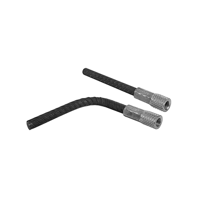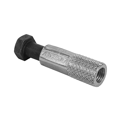

Fixagran® Exclusive Solutions
Fixing solution for granite, marble and porcelain tiles in the ventilated façade system.
FEATURES AND ADVANTAGES
- Exclusive solution for installing ventilated façades.
- Reduced preparation and installation time
- Replaces the use of mortar
- Unique system: no other components required for adjustment
- Immediate loading
- High safety and quality of finish
- Accessories that facilitate applications at critical points
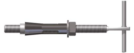
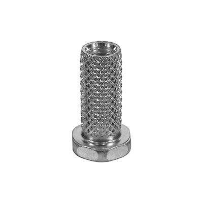
FIXAGRAN - GRM
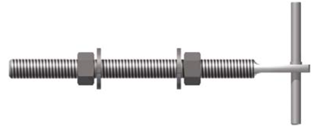
FIXAGRAN ROD - HGR
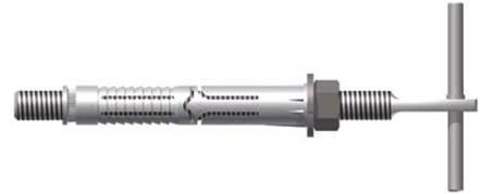
FIXAGRAN ROD - GRN
MAIN APPLICATIONS
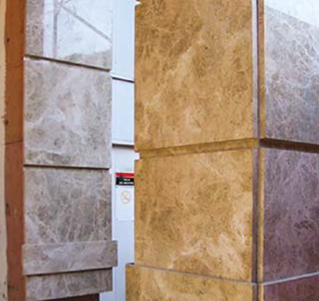
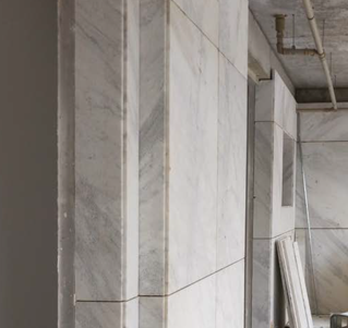
- Ventilated façade (porcelain tiles, granite, marble and panels)
- Cladding pillars, walls and ceilings
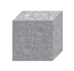
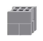
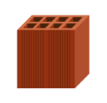


FIXAGRAN® COMPONENTS
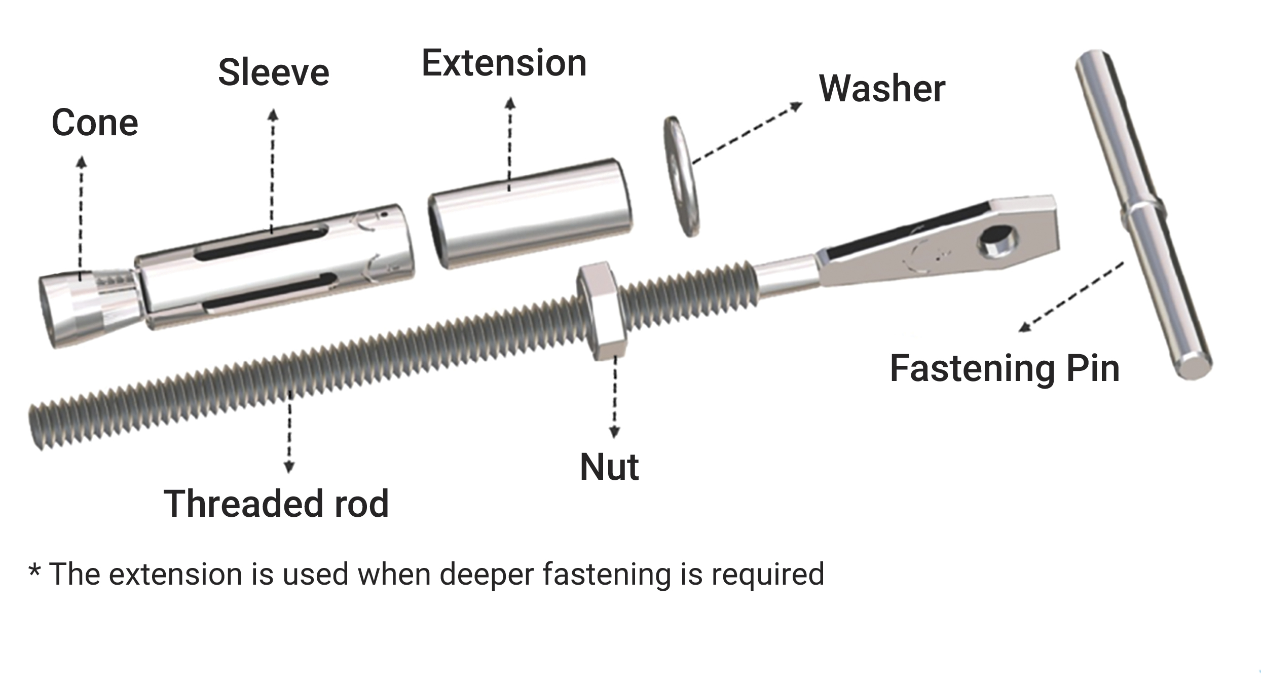
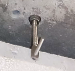
**For masonry applications, the metal sleeve can be replaced by a nylon sleeve or by using chemical anchors.
FIXING PIN DETAILING
For the correct use of Fixagran®, it is essential to know the material that will be used as the façade cladding and its thickness in order to correctly specify the fixing pin. For porcelain tiles, ceramics and slabs between 11 and 20 mm, we recommend using a 3 mm diameter pin. For use with granite and other tiles over 20 mm, a 5 mm diameter pin is recommended.
FIXING GRANITE SLABS, MARBLE. CERAMIC AND PORCELAIN TILES
The Fixagran® system is a high-tech concept product developed for fixing ventilated façades and covering other elements to concrete. It can be used with ceramic tiles, porcelain tiles, granite and marble slabs as a closing element on the façade or as an adornment on the cladding of concrete pillars and walls. Its standard model is made up of stainless steel metal elements, providing the fixture with greater durability and useful life when applied in areas with variations in temperature, humidity, climate change and the incidence of salt spray. The simplicity of its system means it can be installed quickly and efficiently on surfaces such as concrete, steel and masonry, making it easier to adjust and distance the plate used, allowing imperfections in plumb and alignment to be corrected. It offers a minimum distance of 2 cm between the plate and the base.
Differently from the conventional system using mortar, the ventilated façade system using Fixagran® offers major construction advantages. Among these are the reduction in energy consumption in the building by air conditioning equipment, since it allows natural and continuous ventilation of the building wall, and the possibility of placing electrical, plumbing and sanitary installations in the space created between the wall and the cladding, increasing the internal space within the building. Another characteristic advantage of the system is the reduced need for interventions and restorations due to cracks and detachment of slabs compared to the mortar system. The ease of assembly even allows for a quick and complete renovation of the building, with the replacement and redesign of the slabs, completely changing its external appearance.
SIZING METHODOLOGY
In order to guarantee the safety and performance of the Fixagran® system, as well as cost-effectiveness, it is essential to size the fasteners correctly. Recommendations for use may vary according to the size, weight and density of the board, as well as the distance between the board and the wall. The following graph illustrates the relationship between weight and distance to help choose the ideal Fixagran® diameter for the application in question.
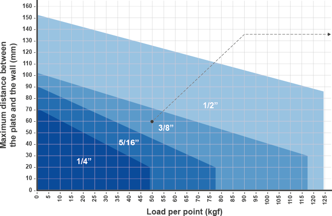
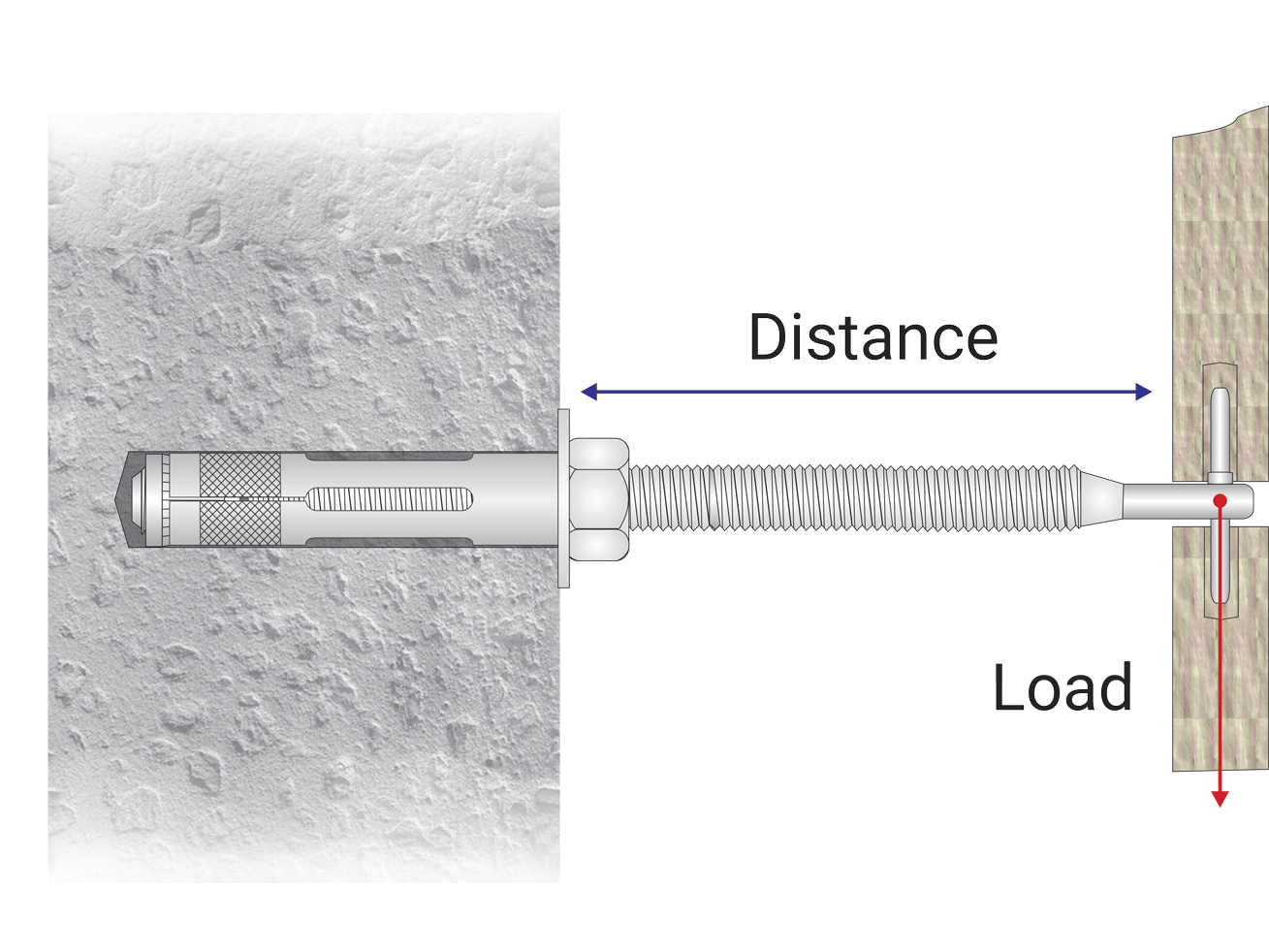
- Check the weight of the plate, identify how many points will be needed to support it and determine the load per fixing point (usually 2 points per plate).
- Check the maximum distance required between the board and the wall according to plumb and alignment.
- With this information, check the chart for the correct size of FIXAGRAN to use, looking at the load and the distance found.

SYSTEM COMPLEMENT
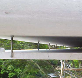
To assist in the assembly process at critical points (such as the bottom of the beam, beam closure, start plate, end plate, etc.), the Fixagran® system has exclusive components.
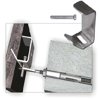
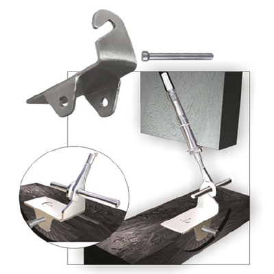
PLUG-IN SUPPORT
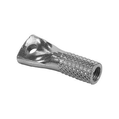
Used for closing beam corners and in situations that require the plate to be removed at a later date.
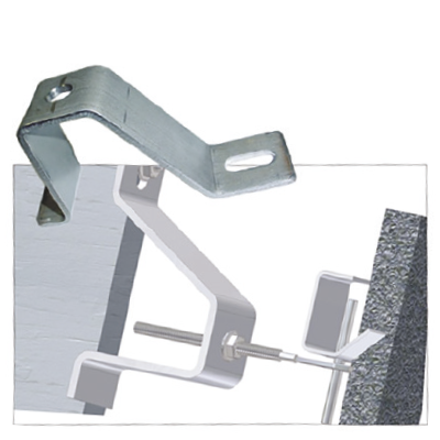
TOP HAT
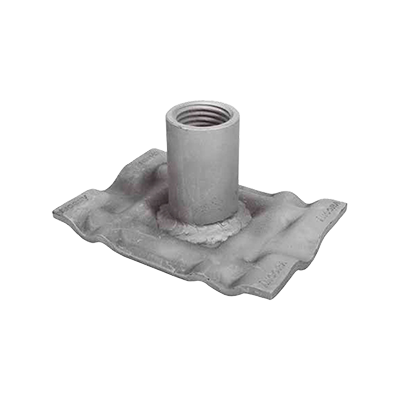
Used to bridge large distances between the wall and the plate to be fixed.
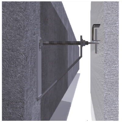
SUPPORT BRACKET
Used for longer distances, allowing the resistance load to be increased with smaller diameter rods.
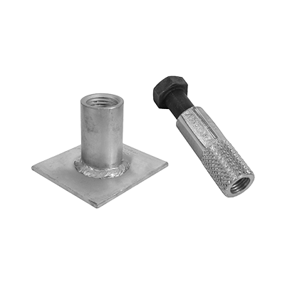
DOUBLE SUPPORT
Used to make the bottom of beams and also for closing slabs.
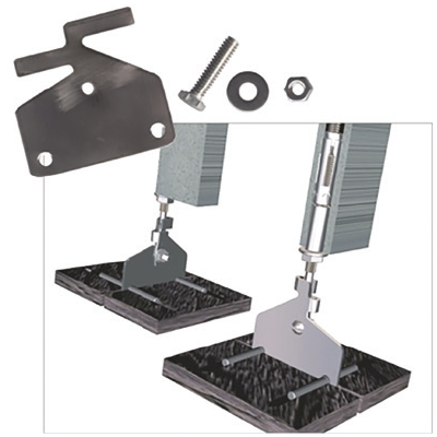
ENDPOINT SUPPORT
Used to fix the last plate to the bottom of the beam.
APPLICATION METHOD
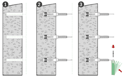
- Make the markings according to the project layout
- Once installed, adjust the rods to the required plumb line
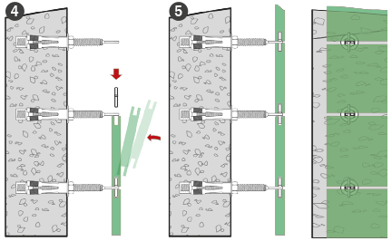
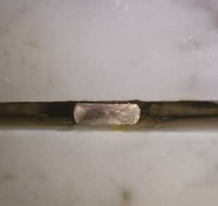
- Position the plate by aligning the holes with the Fixagran and lock it with the pins
- Position the next plate over the pins already in place and repeat the procedure from the previous step
- Proceed with the placement of the other plates, repeating the assembly procedures


FIXAGRAN GRM ANCHOR BOLTS
| Code | Reference diameter | Length | Hole | Wrench (inch) | Ultimate tensile loads² (kgf) | ||
|---|---|---|---|---|---|---|---|
| Thread (inch) | Rod (mm) | Sleeve (mm) | Diameter (in - mm) |
Minimum depth¹ (mm) | Concrete | ||
| GRM14130I | 1/4" | 130 | 34 | 5/16" - 8 | 40 | 7/16" | 1.085 |
| GRM56140I | 5/16" | 140 | 42 | 3/8" - 10 | 50 | 1/2" | 1.550 |
| GRM38150I | 3/8" | 150 | 50 | 1/2" - 13 | 55 | 9/16" | 2.450 |
| GRM38200I | 200 | ||||||
| GRM12160I | 1/2" | 160 | 50 | 5/8" - 16 | 55 | 3/4" | 3.020 |
| GRM12220I | 220 | ||||||
| GRM12250I | 250 | ||||||
FIXAGRAN GRN ANCHOR BOLTS
| Code | Reference diameter | Length | Hole | Wrench (inch) | Ultimate tensile loads² (kgf) | ||
|---|---|---|---|---|---|---|---|
| Thread (inch) | Rod (mm) | Sleeve (mm) | Diameter (in - mm) |
Minimum depth¹ (mm) | Masonry | ||
| GRN14130IL | 1/4" | 130 | 70 | 3/8" - 10 | 80 | 7/16" | 214 |
| GRN56140IL | 5/16" | 140 | 75 | 1/2" - 13 | 90 | 1/2" | 255 |
| GRN38150IL | 3/8" | 150 | 80 | 9/16" - 14 | 95 | 9/16" | 268 |
| GRN38200IL | 200 | ||||||
| GRN12160IL | 1/2" | 160 | 102 | 3/4" - 19 | 120 | 3/4" | 367 |
| GRN12220IL | 220 | ||||||
| GRN12250IL | 250 | ||||||